- 您现在的位置:买卖IC网 > Sheet目录325 > FAN5702UC30X (Fairchild Semiconductor)IC LED DVR 6LED 30MA I2C 16WLCSP
�� �
�
Circuit� Description�
�The� FAN5702� is� a� white� LED� driver� system� based� on� an�
�adaptive� 1.5x� charge� pump� capable� of� supplying� up� to� 180mA�
�of� total� output� current.� The� tightly� matched� current� sinks�
�ensure� uniform� brightness� between� the� LEDs.� Each� LED� has�
�a� common� anode� configuration� with� its� peak� drive� current� set�
�Register� Controlled� Brightness�
�The� DC� value� of� the� LED� current� is� modulated� according� to�
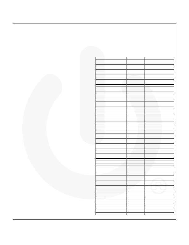
�the� values� in� Table� 1.� Current� is� expressed� as� a� percentage� of�
�the� full� scale� current� and� is� illustrated� with� a� 20mA� I� SET� .�
�during� manufacturing� (� see� Ordering� Information� and� I� SET� ).� An�
�I� 2� C-compatible� interface� is� used� to� vary� the� brightness� within�
�the� individual� current� sinks� as� well� as� configure� the� grouping.�
�Table� 1.� Brightness� Control�
�Dimming� Code� (Bx5-Bx0)� Current� Level�
�000000� 0.125%�
�I� LED� (mA)� (I� SET� =20mA)�
�0.025�
�Each� LED� is� controlled� with� 64� exponentially� spaced� analog�
�brightness� control� levels� through� I� 2� C,� as� indicated� in� Table� 1.�
�For� maximum� flexibility,� the� FAN5702� can� be� programmed�
�with� five� independently� controlled� LED� banks;� by� default,�
�arranged� as� 2,1,1,1,1� (first� two� LEDs� represent� Group� A).�
�Through� I� 2� C,� the� device� can� be� reconfigured� to� add� up� to� six�
�LEDs� to� Group� A� as� needed� by� application� requirements.�
�Charge� Pump�
�The� charge� pump� operates� in� either� 1x� mode,� where� V� OUT� is�
�connected� to� V� IN� through� a� bypass� switch,� or� in� 1.5x� mode.�
�The� circuit� operates� in� 1x� mode� until� the� LED� with� the� highest�
�forward� voltage� (V� LED(MAX)� )� can� no� longer� maintain� current�
�regulation.� At� that� point,� 1.5x� mode� begins.� If� the� lowest� active�
�cathode� voltage� is� greater� than� 1.8V,� the� charge� pump�
�switches� back� to� 1x� mode.�
�IC� Enable�
�By� default� the� General� Purpose� register� bit� 7� =� 0,� the� EN� pin�
�functions� as� enable/disable.� When� the� EN� pin� is� LOW,� all�
�circuit� functions,� including� I� 2� C,� are� disabled� and� the� registers�
�are� set� to� their� default� values.�
�When� the� EN� pin� HIGH,� I� 2� C� interface� is� enabled.� The� LEDs�
�can� be� turned� on/off� by� writing� to� the� General� Purpose�
�register.� The� user� can� always� communicate� via� I� 2� C� with� the�
�device� to� change� register� settings� regardless� of� whether� any�
�LED� is� on� or� off.�
�PWM� Dimming�
�By� programming� the� General� Purpose� register� bit� 7� =� 1,� the�
�EN� pin� is� reappropriated� to� a� PWM� dimming� input.� Applying� a�
�PWM� signal� to� this� pin� controls� the� LED� current� waveform� to�
�be� ON� when� the� PWM� dimming� pin� is� HIGH� and� OFF� when�
�the� PWM� dimming� pin� is� LOW.� By� using� this� pin� in� conjunction�
�with� the� I� 2� C� register� dimming,� the� part� can� achieve� higher�
�dimming� resolution.� For� instance,� an� 8-bit� PWM� dimming�
�signal� applied� along� with� the� 6-bit� register� dimming� yields�
�better� than� 14� bits� of� resolution�
�To� change� the� PWM� dimming� pin� back� to� the� EN� function,� set�
�the� General� Purpose� register� bit� 7� to� 0.�
�000001�
�000010�
�000011�
�000100�
�000101�
�000110�
�000111�
�001000�
�001001�
�001010�
�001011�
�001100�
�001101�
�001110�
�001111�
�010000�
�010001�
�010010�
�010011�
�010100�
�010101�
�010110�
�010111�
�011000�
�011001�
�011010�
�011011�
�011100�
�011101�
�011110�
�011111�
�100000�
�100001�
�100010�
�100011�
�100100�
�100101�
�100110�
�100111�
�101000�
�101001�
�101010�
�101011�
�101100�
�101101�
�101110�
�101111�
�110000�
�110001�
�110010�
�110011�
�110100�
�110101�
�110110�
�110111�
�111000�
�111001�
�111010�
�111011�
�111100�
�111101�
�111110�
�111111�
�0.188%�
�0.249%�
�0.312%�
�0.374%�
�0.438%�
�0.499%�
�0.560%�
�0.622%�
�0.692%�
�0.750%�
�0.810%�
�0.875%�
�0.938%�
�1.004%�
�1.124%�
�1.250%�
�1.375%�
�1.499%�
�1.625%�
�1.750%�
�1.881%�
�2.063%�
�2.249%�
�2.438%�
�2.687%�
�2.939%�
�3.186%�
�3.562%�
�3.936%�
�4.310%�
�4.813%�
�5.314%�
�5.936%�
�6.565%�
�7.313%�
�8.059%�
�8.938%�
�9.876%�
�10.874%�
�12.005%�
�13.253%�
�14.618%�
�16.124%�
�17.881%�
�19.875%�
�22.121%�
�24.621%�
�27.376%�
�30.373%�
�33.623%�
�37.124%�
�40.873%�
�44.875%�
�49.124%�
�53.624%�
�58.375%�
�63.378%�
�68.625%�
�74.122%�
�79.874%�
�85.873%�
�92.373%�
�100.000%�
�0.038�
�0.050�
�0.063�
�0.075�
�0.088�
�0.100�
�0.113�
�0.125�
�0.138�
�0.150�
�0.163�
�0.175�
�0.188�
�0.200�
�0.225�
�0.250�
�0.275�
�0.300�
�0.325�
�0.350�
�0.375�
�0.413�
�0.450�
�0.488�
�0.538�
�0.588�
�0.638�
�0.713�
�0.788�
�0.863�
�0.963�
�1.063�
�1.188�
�1.313�
�1.463�
�1.613�
�1.788�
�1.975�
�2.175�
�2.400�
�2.650�
�2.925�
�3.225�
�3.575�
�3.975�
�4.425�
�4.925�
�5.475�
�6.075�
�6.725�
�7.425�
�8.175�
�8.975�
�9.825�
�10.725�
�11.675�
�12.675�
�13.725�
�14.825�
�15.975�
�17.175�
�18.475�
�20.000�
�?� 2010� Fairchild� Semiconductor� Corporation�
�FAN5702� ?� Rev.� 1.0.4�
�12�
�www.fairchildsemi.com�
�发布紧急采购,3分钟左右您将得到回复。
相关PDF资料
FAN7080MX_GF085
IC GATE DRIVER HALF BRIDGE 8SOIC
FAN7081MX_GF085
IC GATE DRIVER HI SIDE 8-SOIC
FAN7083MX_GF085
IC GATE DVR HI SIDE RESET 8-SOIC
FAN7085M_GF085
IC GATE DVR HI SIDE 8-SOIC
FAN7171MX_F085
IC GATE DVR HIGH SIDE 8-SOIC
FAN7190MX
IC GATE DVR HI/LOW SIDE 8-SOIC
FAN7340MX
IC DVR BOOST SW LED BKLT 16-SOIC
FAN7346MX
IC LED DRVR 4 CHAN BLU 28SOIC
相关代理商/技术参数
FAN5702UMP08X
功能描述:LED照明驱动器 Config. 180mA 6-LED Driver w/I2C Control
RoHS:否 制造商:STMicroelectronics 输入电压:11.5 V to 23 V 工作频率: 最大电源电流:1.7 mA 输出电流: 最大工作温度: 安装风格:SMD/SMT 封装 / 箱体:SO-16N
FAN5702UMP15X
功能描述:LED照明驱动器 Config. 180mA 6-LED Driver w/I2C Control
RoHS:否 制造商:STMicroelectronics 输入电压:11.5 V to 23 V 工作频率: 最大电源电流:1.7 mA 输出电流: 最大工作温度: 安装风格:SMD/SMT 封装 / 箱体:SO-16N
FAN5702UMP20X
功能描述:LED照明驱动器 Config. 180mA 6-LED Driver w/I2C Control
RoHS:否 制造商:STMicroelectronics 输入电压:11.5 V to 23 V 工作频率: 最大电源电流:1.7 mA 输出电流: 最大工作温度: 安装风格:SMD/SMT 封装 / 箱体:SO-16N
FAN5702UMP30X
功能描述:LED照明驱动器 Config. 180mA 6-LED Driver w/I2C Control
RoHS:否 制造商:STMicroelectronics 输入电压:11.5 V to 23 V 工作频率: 最大电源电流:1.7 mA 输出电流: 最大工作温度: 安装风格:SMD/SMT 封装 / 箱体:SO-16N
FAN5902
制造商:FAIRCHILD 制造商全称:Fairchild Semiconductor 功能描述:800mA Buck Converter for 3G RFPAs
FAN5902MPX
功能描述:直流/直流开关转换器 800mA Buck Converter for 3G RFPAs RoHS:否 制造商:STMicroelectronics 最大输入电压:4.5 V 开关频率:1.5 MHz 输出电压:4.6 V 输出电流:250 mA 输出端数量:2 最大工作温度:+ 85 C 安装风格:SMD/SMT
FAN5902UCX
功能描述:直流/直流开关转换器 ANG FG RoHS:否 制造商:STMicroelectronics 最大输入电压:4.5 V 开关频率:1.5 MHz 输出电压:4.6 V 输出电流:250 mA 输出端数量:2 最大工作温度:+ 85 C 安装风格:SMD/SMT
FAN5903
制造商:FAIRCHILD 制造商全称:Fairchild Semiconductor 功能描述:Buck Converter with Bypass Mode for 3 G / 3.5 G / 4 G PAs